A practical SLAM mapping robot should be evaluated as a complete field system, not by its mapping demonstration alone. At Direct Drive Tech, we recommend checking five areas: whether the robot can travel the actual route, carry and power the sensor package, expose the required ROS 2 interfaces, deliver the point-cloud, camera, odometry, and positioning data your workflow needs, and repeat the run within the available operating time. TITA with TITA Tower brings these elements together, but the final decision should come from route-specific testing and confirmed mapping requirements.
Evaluate the Complete System, Not Just the SLAM Stack
Several capabilities that once required separate integration projects can now sit on the same mobile platform. Our TITA platform includes NVIDIA Jetson Orin NX 16GB computing, ROS 2 development support, and SDK/API access. These documented interfaces give your team a starting point for integrating perception, motion, and application software without first building the base platform from separate components.
Check whether the platform can the platform can carry and power the required sensor package. TITA Bridge provides an attachment path for external accessories, while hot-swappable batteries support about one hour per battery and about two hours with the set, depending on load and motion. Together, these features reduce the basic platform work required before field testing, although application-specific mounting and software integration are still required.
A Practical Mapping Robot Is More Than a LiDAR on Wheels
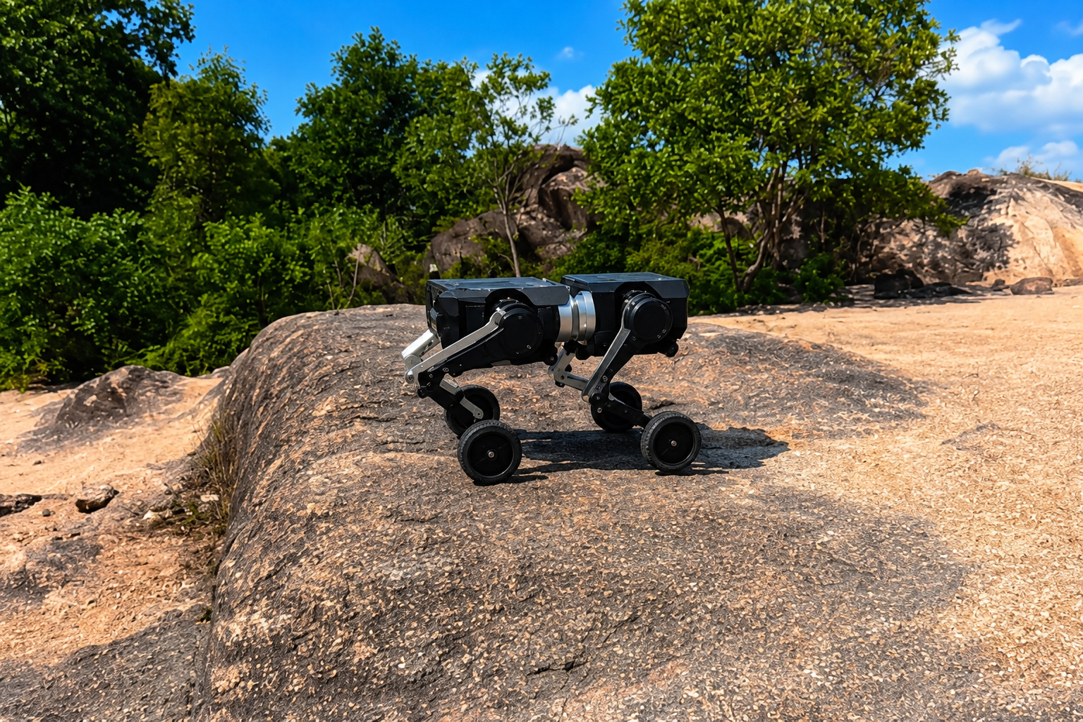
LiDAR and cameras describe the surroundings, but a field-ready mapping robot also needs stable locomotion, route control, computing, power, payload capacity, and accessible interfaces. With TITA's 8-DoF wheeled bipedal structure, we combine efficient wheel motion across open areas with leg movement for route transitions. This matters on sites with thresholds, slopes, uneven paving, cable covers, and changes between indoor and outdoor surfaces.
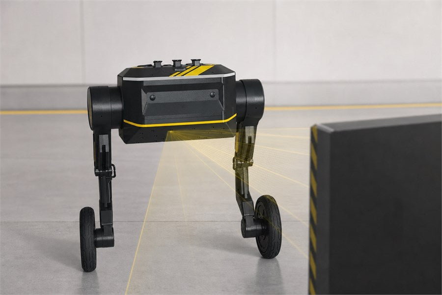
We also use TITA Terrain Awareness as a perception layer for mobile work. Its binocular structure collects real-time 3D object data, and the official product description lists mm-level accuracy, high stability, and resistance to environmental light interference. We do not treat that specification as proof that every completed map meets engineering-survey tolerances. Final accuracy still depends on calibration, sensor placement, site conditions, data processing, and the project's acceptance criteria.
What TITA Tower Adds to a Site-Survey Workflow
With TITA Tower, we publish high-precision odometry, colored mapping point clouds, left and right camera streams, and RTK data in China or GPS data outside China through ROS 2. The colored point cloud can be viewed in RViz 2, while the documented ROS 2 topics can be integrated into an inspection or site-survey workflow. Confirm how each project will each project will handle data storage, alignment across runs, comparison, and reporting. If the project requires map saving, loop closure, relocalization, or a specific final mapping accuracy, confirm those requirements for the selected configuration before deployment.
Choose the TITA Configuration Around the Route and Sensor Load
Define the required deliverable before selecting hardware. A progress check may need a colored point cloud and camera views from the same path, while a facility layout update may require spatial data with a position reference. For asset inspection, the visual record should remain associated with the relevant location.
Maximum speed is rarely the deciding factor for inspection mapping. The TITA Specification lists a standard maximum speed of 3 m/s, with up to 5 m/s available through API unlock when the project environment and safety controls are suitable. It also lists a 10 kg moving payload and a maximum slope of +/-30 degrees. These are platform limits, not a substitute for testing the complete payload on the actual surface.
The official specification lists TITA Tower, High Capacity Battery, 18 Inch Big Wheels, and Power Adapter Module (Robot Arm Base) as add-ons. We recommend choosing among them according to route length, ground conditions, sensor load, power needs, and mounting requirements rather than one headline specification.
Plan the Pilot Around Real Field Conditions
Test the Actual Working Route
We start a serious evaluation with the route the robot will actually use. A clean test area cannot represent reflective materials, dust, repeated corridor patterns, temporary obstacles, mixed lighting, or indoor-outdoor transitions. Select a representative section with the narrowest clearance, a typical slope or threshold, normal surface changes, and at least one useful inspection or survey point.
Check the Setup Before Field Evaluation
We also verify the setup before judging field performance. The TITA Tower User Manual states that the tower is powered through TITA's DB25 external interface, requires the officially certified DB25 connection cable, and must not be hot-plugged. ROS_DOMAIN_ID, Ethernet configuration, device communication, and data topics should be checked before the field run.
Measure Repeatability Before a Full-Site Trial
During the pilot, we recommend recording route length, terrain, total sensor payload, required output, target operating time, and takeover method. Then compare route completion, point-cloud output, camera-stream quality, battery handling, data export, and consistency across repeated runs. If your workflow depends on map reuse or relocalization, test those functions explicitly rather than assuming they are included. The decision is simple: can this configuration produce the required site data repeatedly on the intended route?
Use the TITA Tutorials and official manuals during setup. When you contact our team, share the route constraints, terrain, sensor payload, required point-cloud or image output, and target runtime. We can then discuss platform configuration, mounting, power, and software integration before a larger trial.
FAQ
Does a SLAM Mapping Robot Always Need LiDAR?
We do not treat LiDAR as the only useful input. Cameras add color and visual detail, while IMUs, odometry, RTK, or GPS can support motion estimation or positioning context. We recommend choosing the sensor mix according to the environment and the required deliverable.
Can a SLAM Robot Replace Conventional Surveying Equipment?
We do not position a SLAM robot as an automatic replacement for conventional surveying equipment. It can make repeated site-data collection, progress monitoring, and inspection-route documentation more efficient, but replacement is appropriate only when the complete system meets the project's accuracy, calibration, repeatability, and reporting requirements.
When Is TITA a Good Fit for Inspection Mapping?
We recommend TITA when your project needs repeated inspection or site-survey routes, ROS 2 development access, payload capacity for a mapping setup, and structured outputs from TITA Tower. It is particularly relevant when mixed surfaces or route transitions make a flat mobile base less suitable.